
Knowledge · Process
From design to acceptance — the stages of building an MV cable line
How a medium-voltage cable line is built — from the topographic survey to handing the network over for operation. Stage by stage.
A cable line that is invisible once the work is finished is the result of work by designers, surveyors, builders, the electrical testing laboratory and the operator's services. For a customer or owner's engineer, understanding the stages helps plan a realistic schedule, anticipate risks and know which documents to expect at the end. Below we describe the typical course of building a 6–30 kV cable line in Ukraine. The exact sequence depends on the customer, the DSO and the facility's consequence class.
Stage 1: input data and topographic survey
The starting point is a need: supplying a new development or business, connecting generation, undergrounding a fault-prone overhead section, relocating networks out of a construction zone. For connections the basis is the DSO's connection conditions; for the operator's own works, its network development plans and technical requirements. The customer issues a design brief.
The designer commissions a topographic survey of the route — usually at 1:500, showing existing underground utilities. On this basis they analyse route options, crossings with other networks, obstacles (roads, rivers, railways, green areas) and land ownership.
Decisions that determine cost and timing are already made here. A route along roads and streets makes access and approvals with land users easier, but needs road owners' approvals and often more HDD crossings. A route across private plots can be shorter, but needs the consent of many owners.
Stage 2: design and approvals
The design sets the route, the cable type and cross-section, the laying method, the locations of joints, substations and switching stations, HDD crossings, connection points with the existing network and the scope of landscaping reinstatement. Cables and accessories must meet the requirements of the PUE (Ukrainian Electrical Installation Rules), the DBN (state building codes) and the technical requirements of the DSO that will accept the line.
During design, the following are usually obtained:
- consents of land owners and users to lay the line and, where needed, a servitude is registered;
- road owners' approvals for placing the cable within the right-of-way and for the method of crossing the carriageway;
- approvals from the owners of other utilities — water, sewerage, gas, district heating, telecoms;
- approvals from local authorities for the route within a settlement;
- where needed, approvals from Ukrzaliznytsia (Ukrainian Railways), owners of water bodies, forest users and cultural heritage authorities.
The design is approved by the DSO. For facilities of consequence class CC2 and CC3, a design review is carried out. The right to carry out construction works is obtained in the manner set by the urban planning legislation — by notification or permit depending on the consequence class, through the Unified State Electronic System for Construction.
Stage 3: preparing for construction
- reviewing the design and bill of quantities, checking the route on site;
- survey setting-out of the route, HDD locations and equipment;
- obtaining excavation permits and approving traffic management plans for the duration of works;
- calling in representatives of utility owners to confirm their location on site;
- ordering cables, accessories, ducts and substations — taking drum lengths into account to reduce the number of joints;
- arranging staff authorisation and work permits (naryad-dopusk) for work in the protection zones of live installations.
It is also worth agreeing ground rules with the customer, owner's supervision and the DSO: who approves route changes caused by site conditions, how outages are requested, how progress is reported and which certificates are signed during construction.
Stage 4: earthworks and HDD
Where possible, the cable is laid in an open trench dug by excavator, and by hand near existing utilities. At crossings, trial pits are dug to confirm the position of networks.
Under roads, railways, rivers and driveways, HDD or pipe ramming is carried out with protective ducts pulled in. How HDD works is explained in the article How horizontal directional drilling works.
The trench bottom is levelled and a bedding of sand or fine soil is laid. Trenches are dug in compliance with occupational safety requirements: shoring or battered sides, barriers, lighting and, on roads, an approved traffic management plan.
Stage 5: cable laying
Cables arrive on drums, are unloaded with a loader crane and mounted on drum jacks. The cable is rolled out by hand over rollers or pulled by winch — especially in ducts and on long sections — with the pulling force and bending radius monitored.
The three single-core cables are laid as per the design, most often in trefoil. Before backfilling, an as-built survey of the cable position is carried out and a certificate of concealed works is signed. The cable is then covered with sand, warning tape or protective elements are laid, the trench is backfilled with compaction in layers, and the surface and landscaping are reinstated.
Stage 6: installing accessories and equipment
- straight joints between drum lengths and transition joints where the line connects to existing paper-insulated cables;
- substations and switching stations, if they are within the scope of works;
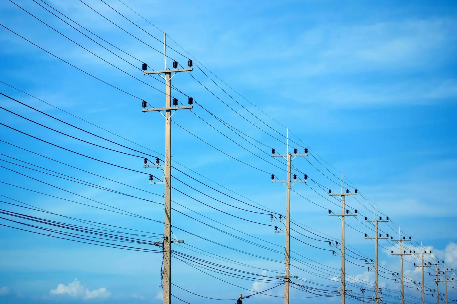
- terminations in switchgear panels and on poles where the cable line connects to an overhead line (together with surge arresters).
Installing accessories requires cleanliness, precision and strict adherence to the manufacturer's instructions. Joint locations are recorded in the as-built documentation.
Stage 7: testing and connection
Before energisation, an electrical testing laboratory carries out acceptance tests to the extent required by the PUE, the testing standards, the design and the DSO. These usually include:
| Test | Purpose |
|---|---|
| Conductor and screen continuity check, phasing | confirming the connections are correct |
| Insulation resistance measurement | detecting moisture or damage |
| High-voltage insulation test | for XLPE cables — usually with very low frequency (VLF) voltage |
| Sheath test | detecting sheath damage from laying and backfilling |
| Earthing resistance measurement | confirming the required earthing resistance of substations, switching stations and poles |
The results are recorded in test reports. The operator then connects the new line according to its procedures and at an agreed outage time. If the job involves undergrounding, the old overhead line is then removed.
Stage 8: as-built documentation and acceptance
The contractor hands the customer the as-built documentation, which usually contains:
- working drawings with the changes marked;
- certificates of concealed works and the works log;
- the as-built survey showing the position of cables, joints and HDD crossings;
- measurement and test reports;
- certificates and data sheets for the cables, accessories and equipment;
- documents on landscaping reinstatement and closing the excavation permits.
After the DSO's technical acceptance (if the line is transferred to the operator) and the issue of the document confirming the facility's readiness for operation, the line is put into service; the contractual warranty period usually starts from this point. Gaps in documentation are one of the most common reasons for drawn-out acceptance, so it is best compiled as the work progresses rather than after completion.
What affects the schedule
Design and approvals usually take longest — especially when the route crosses many plots. Construction itself can be relatively short, but its duration is affected by the number of HDD crossings and the soil, the weather, outage dates, material availability, road restrictions and the extent of old-network removal.
Earthworks and cable laying can be carried out for most of the year, but in winter frozen ground and the cable's minimum laying temperature have to be taken into account, and in the growing season, crops along the route. A well-prepared site — with a full set of approvals, the route set out and materials ordered — reduces these risks.
How we work at each stage is described on the How we work page, and our list of services on the MV and LV cable lines page.
See also
Read next
How we work
Stages of building MV/LV cable lines and substations at BUDNORM: pricing, preparation, works, measurements, as-built documentation and DSO acceptance.
Learn moreMV and LV cable lines
Construction, reconstruction and repair of 6–30 kV MV and 0.4 kV LV cable lines: trenches, HDD, cable laying, joints, cabinets, testing and acceptance.
Learn moreMV cables with XLPE insulation
XLPE-insulated MV cables: construction, how to read АПвЕгП, АПвЕВ and АПвП designations, cross-sections, voltage classes and where each is used.
Learn moreHave an MV cable line design?
We will review the documentation and site conditions and prepare a proposal with a schedule — from trenching to acceptance.